50V to 14V Regulator

I use an external 50V power supply for my amplifiers, the ESP 120.  This gets a clean, powerful, well regulated 50V into the enclosure for the RF Pallet.

In the essence of keeping everything as simple as possible, I tap off of this 50V and regulate down to 14V to power the low power circuits, like the relay sequencer and the relays themselves.

This sounds trivial, right? I initially thought so, however I found it challenging because I did not want a regulator that runs hot and requires a lot of heat sinking.

The challenge is the voltage drop of 36V (50V to 14V), times the current delivered (P=EI) has to be dissipated as heat in the regulator.

At just 1A, you’re looking at 36W dissipated as heat, which will easily put a pass transistor into thermal runaway without a substantial heatsink.

Many designers will use a synchronous step down regulator, also known as a buck regulator. I did not want that complexity in my amp.

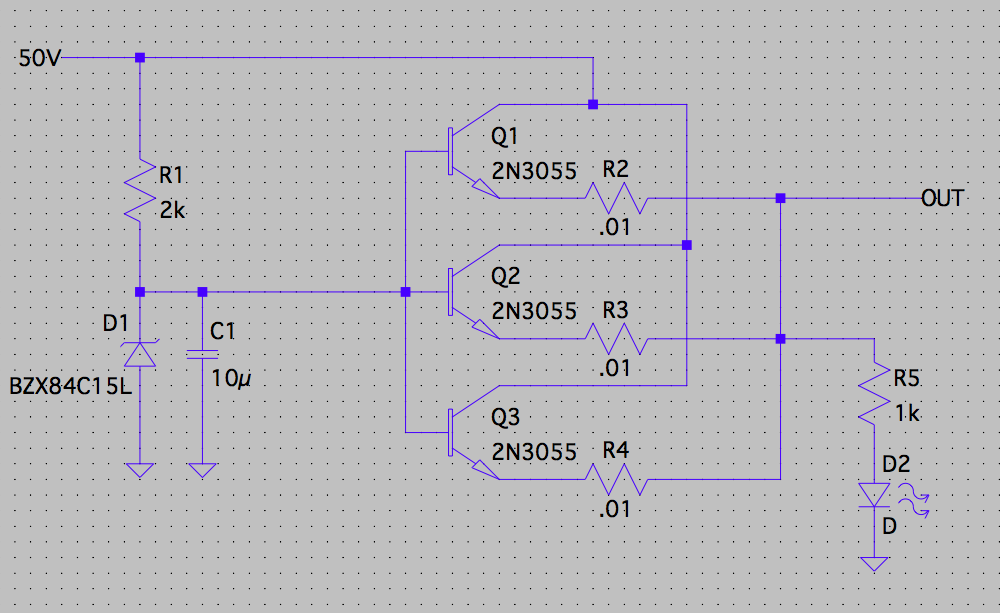
Instead, I took a hybrid approach of spreading the current across three extremely overrated pass transistors, and dropping the 50V to a lower voltage across a large power resistor prior to the regulator.

Admittedly, this would be a fairly poor design if you had to deliver large currents into varying loads. However, it’s perfectly acceptable and predictable if you know your maximum load current. In this case, it’s just under 1A, so the voltage drop in the power resistor is still well above 14V and the regulator functions well.

Basically, this is designing for a very specific application and every power supply internal to a product, or integrated onto a PCB is designed exactly like this – for the specific purpose.

The resulting regulator runs ice cold while powering the LED and relay sequencer board. If you go key down and energize the relays it just barely gets warm after about five minutes and never gets any hotter.
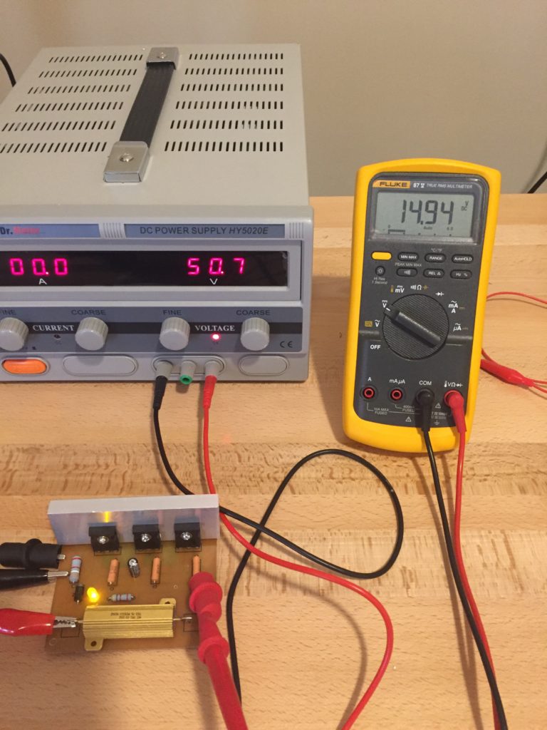
 

Testing the regulator. Ultimately I gave it a 2A load and let it sit for a couple of hours. This is over 2x the current it will ever see while energizing two relays.


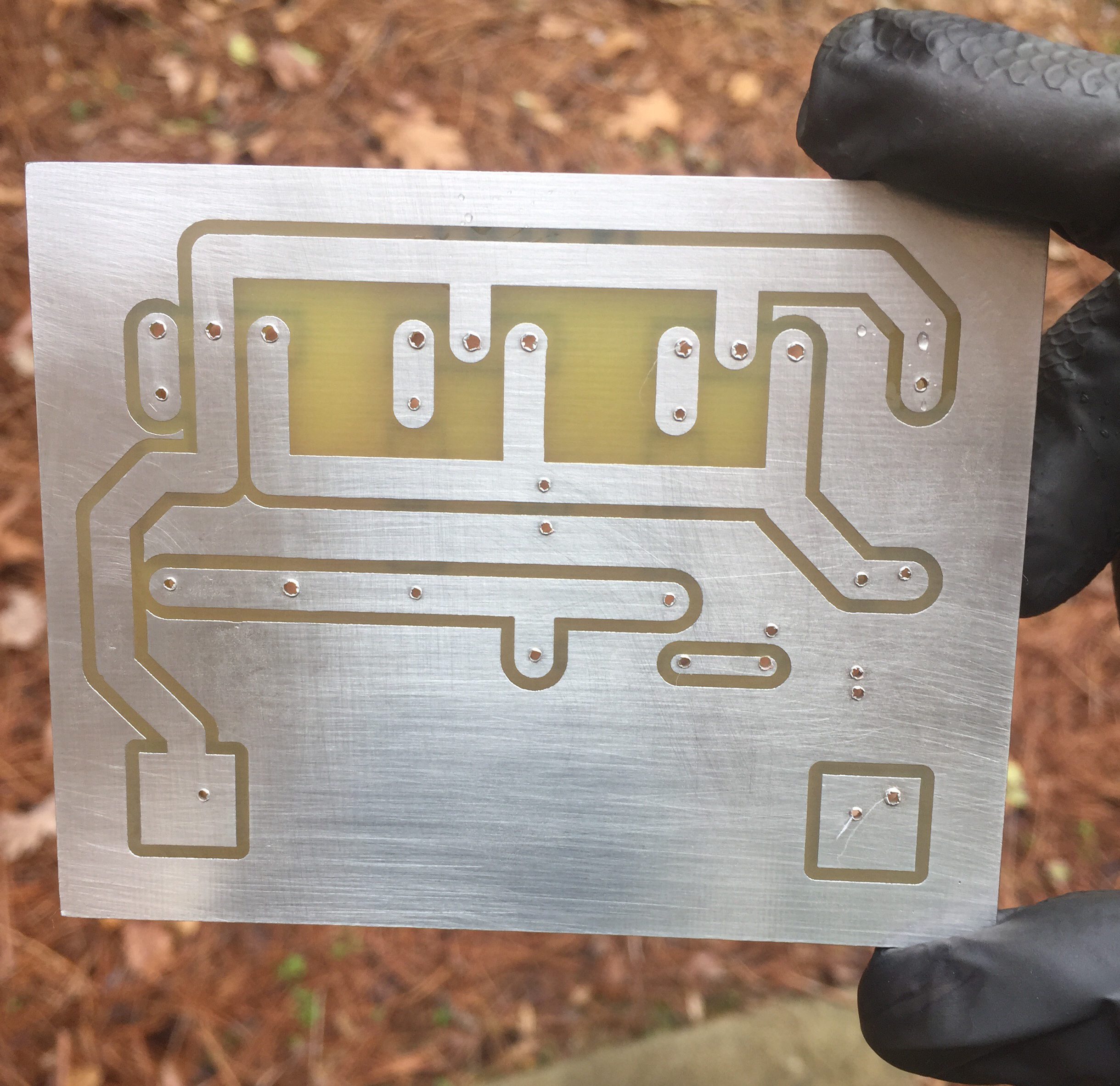
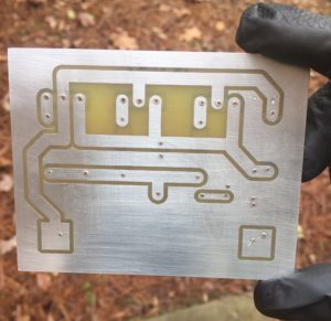
Making the PCBs is half the fun..


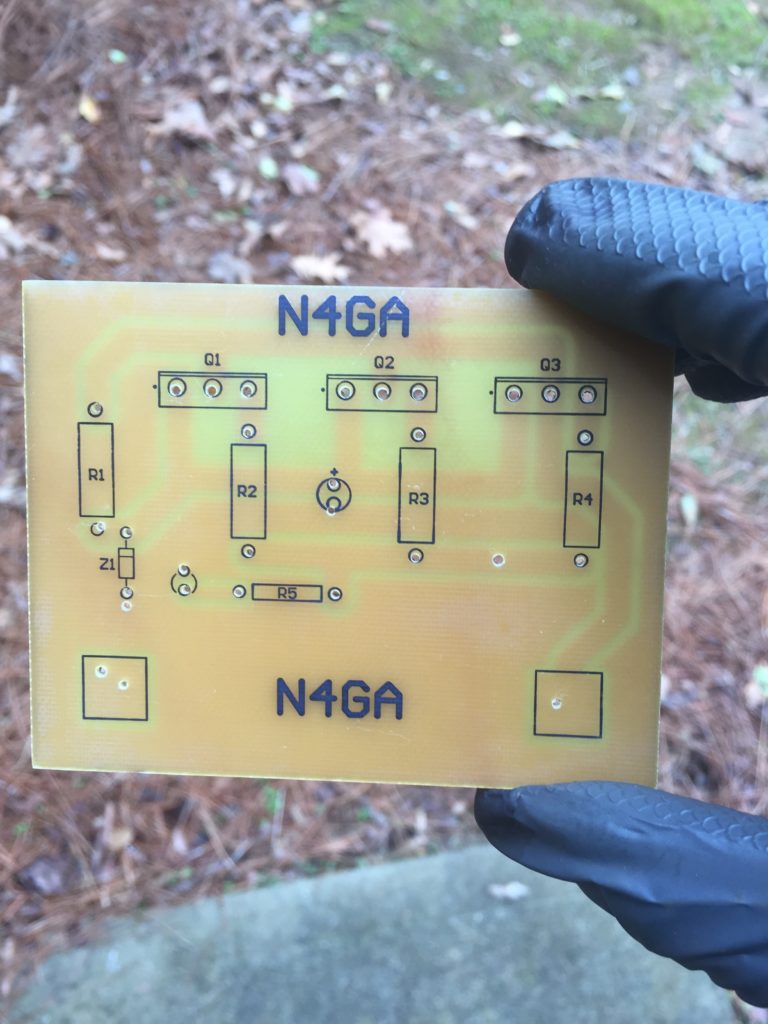
Tried to get fancy on this little PCB and do a silkscreen on the top. Came out surprisingly well, but probably not worth the effort.


D1 is a Zener. Just make it about a volt higher than you want as an output.

Q1-3 can be any NPN high current capable pass transistors.


Comments

19 responses to “50V to 14V Regulator”

  1. N4GA Avatar
    N4GA

    Hi Mike. I’ll try to get the schematic up this weekend. It’s a super simple schematic.

  2. thomas Avatar
    thomas

    n4ga, hello bud, It’s kj4zdb. I am about to be working on a Dual BLF188xr Legal Limit Amplifier and my question is, are you not running the Bias from this board as well?

    I am needing a solution to run my Bias, LEDs and Relays as well other then adding another 12v Supply or trying to find a server supply with dual output. Because of you I just purchased 2 x ESP120 i believe it was, or ES120 lol. Bad short term memory. So now I just need a solution like this and if I can run my bias, relays and LED off of a board as you have made I will be in GREAT Shape. My Fans are 220v Fans so I am go on those for my case that is.

    Thanks in advance. I can’t wait to see the circuit. I am guessing the Zener diode is a 14v Diode shunted and the 3 Pass Transistors along with equalizing resistors and of course a drop resistor before the zener is what you have going on. Look forward to hearing back from you.

    1. N4GA - Rob Avatar
      N4GA – Rob

      Tom,

      Correct on the 50v to 12v regulator. It’s actually just under 15V as I used a 15V zener, then you have the Vbe drops across the pass transistors. Very simple regulator. This way I can come into the cabinet with 50V and not need an external 12V supply as well.

      I use a simple 4 event delay board for my relays. This is sold by W6PQL, where you can also find a ton of other stuff. Here’s the link.

      The ESP120 is a great supply. Good purchase!

      73

  3. Phil Lohiser Avatar
    Phil Lohiser

    Rob , you are a busy man but wonder if sometime you could just give us a pencil sketch of your 50 to 15v regulator, I pretty well know how you did this but your confirmation would be great , Thanks Phil W8KLK.

  4. Phil Lohiser Avatar
    Phil Lohiser

    Rob , Thank you very much , looks like you used the good old 3055 trans. , those .01 resistors are pretty close to a solid piece of wire , I will put this in notebook and will use it on my LDMOS as it gets close to finished , Thanks again Rob , I just love to follow you guys on Facebook , 73 Phil , W8KLK

    1. N4GA - Rob Avatar
      N4GA – Rob

      Phil,

      I’m sure this circuit can be optimized!

      I just happened to have a bunch of old 3055s. Probably a n-channel MOSFET is a better more modern choice. But this little regulator works great and has never malfunctioned in this harsh RF environment. And I leave it on 24/7.

  5. Thomas KJ4ZDB Avatar
    Thomas KJ4ZDB

    Hello Rob,

    Here I am again, I am so sorry to bother you again bud. I have made up my mind to go ahead and build your circuit and use it for my project. I am using a Meanwell RSP-2000-48 for my Single BLF188XR Amplifier and I was thinking of using the .8A 12 Aux Supply that is offered by this supply via a molex plug of course they don’t supply lol(or atleast I didn’t receive one) but I was thinking, I already have 12v zeners on each of the bias inputs and it would be best to give the bias at least 1 to 2 volts more then 12v at that point.

    Here is my question. You mentioned that you are running your relay sequencer & relays and i’m sure possibly some LEDS if any using this neat 50v to 14v Regulator circuit but you don’t mention the bias voltage at all.

    Are you getting your Bias Voltage from this Regulator that you have made as well? I am guessing yes since you are only using the ESP120(Which thanks to you I have purchased for my next project)

    I have enough Heat sink that I can mount the Pass Transistors on the main heat sink along with the Big Power Resistor as well.

    That was my main Question I wanted to ask, where are you tapping on to for your Bias Voltage Supply?

    Thanks so much buddy. You have been a blessing to me especially with the dummy load project you have done also.

    Thomas KJ4ZDB

    1. N4GA - Rob Avatar
      N4GA – Rob

      Thomas,

      No bother at all! Currently I’m taking 12v from this regulator, going through a relay, then to the RF pallet. The 12v is then regulated down to 6v via a Zener. This goes to the bias circuit.

      I’m currently working on my “next gen” bias circuit which will involve a 3-pin adjustable regulator that tracks the temp of the pallet with a thermistor.

      Rob

      1. Thomas Mize KJ4ZDB Avatar
        Thomas Mize KJ4ZDB

        Awesome, I will be keeping track of your regulated Bias Circuit with temp compensation. Very interesting!

  6. Slava, VE7LWW Avatar
    Slava, VE7LWW

    I think it’s easier to use a DC-DC converter rather than a linear regulator to get the low voltage voltage required for various switching circuits.

    ESP120 have 5V output and we can use it.

    1. N4GA - Rob Avatar
      N4GA – Rob

      Slava,

      Yes, those are good options as well. I removed the links as they will soon be dead links, pointing to completed/removed eBay auctions.

      Thanks!

      1. Slava, VE7LWW Avatar

        Sorry Phil.
        It was not advertising. I only wrote samples of DC-DC converters (5V -> 12V, 50V -> 12V), which we can use for our purposes.
        Success to you. There is a lot of good information on your website.

        1. N4GA - Rob Avatar
          N4GA – Rob

          No problem at all, I did not look at them that closely. I thought were eBay links which will eventually expire, creating dead links on the site.

  7. Michael Martin Avatar
    Michael Martin

    Interesting attempts to regulate from 50V to 12V, but I ran into the issue of regulator components were maxed out of input voltage before 50V. I had tried a series of switching regulators to drop from 50V to 24V for my antenna relays and fans (in series), then 24V to 12V for the LPF, Sequencer and other 12V control stuff. All with poor reliability.

    What I ending up doing is just bringing 12V in off of the radio supply, switching it in the amplifier for the 50V supply control, and all the other 12V stuff.

    1. N4GA - Rob Avatar
      N4GA – Rob

      Mike, thanks for the comments. Hang in there – there are plenty of ways to reliably get from 50V to 12V.

  8. Lyle Dysinger N4QH Avatar
    Lyle Dysinger N4QH

    I have built many LDMOS amps, 160 thru 23 cm and have always used 2 24 volt meanwell supplies for 50 volts. Dropping 24 volts to 12 volts with a simple 3 terminal regulator. And if you go this route, don’t forget to use a small capacitor for the input and output of the regulator.

    1. N4GA - Rob Avatar
      N4GA – Rob

      Yes sir!

      Back when I made that massively over designed regulator, I was just using parts I had on hand here.

      In my list of projects is a 50V to 15V regulator using a LM317HV which can drop a 60V differential. So a 35V differential with a little heat sink should be fine, especially at less than 1 amp required for relays.

      Soon these amps will be down to like 2 parts!

  9. Peter E. Avatar
    Peter E.

    Hi Rob,

    I had the same issue with a 1Kw Mosfet linear I built. Your supply looks very simple and reliable, however pouring 36W of heat into the amp is a bit of a disadvantage. I have just bought a 5A Chinese Buck converter off Ebay and it is compact, cheap and runs dead cold. I have added a fuse and overvoltage protection diode on the output also.

    Cheers, peter – VK2AN

    1. N4GA - Rob Avatar
      N4GA – Rob

      Pete,

      I totally agree!!

      My 14V circuit uses maybe 200mA on key down. Whatever it takes to hold two little G1 relays closed. So 7.4W of heat. And only on TX.

      But yeah, the little Bucks are perfect. I have built some of those. So nice and small!

      Cheers! Rob

Leave a Reply

Your email address will not be published. Required fields are marked *