Jerry Sevick, W2FMI (SK) called this the “Soak Test.” He used it to run real power through the TLT network to check efficiency. It’s a pretty simple test whereby you simply run significant power through the TLTs and measure the temperature rise in the cores. If they get hot, they are not as efficient as they could be.
I’ve found that the soak test can be used for efficiency testing, and it also can be used for general TLT network design and test, as well as compensation capacitor testing.
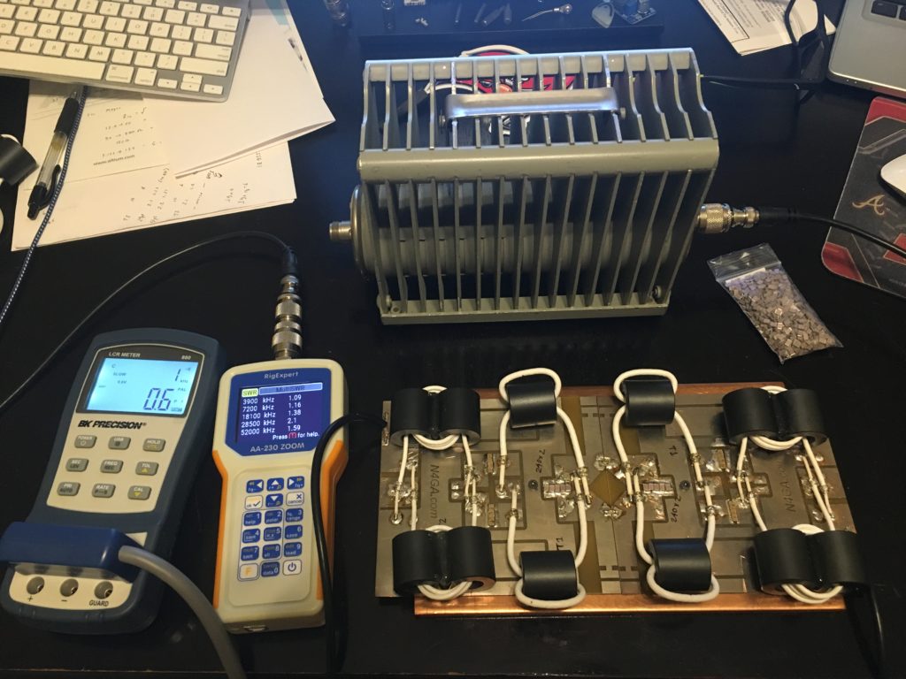
In the photo above, we have two back to back 16:1 Guanella TLTs (parallel inputs, series outputs, no bootstrap). The 16:1 is realized with two back to back 4:1 Guanella TLTs.
The low impedance sides are connected in the center, so you now have 50 ohms on each end. In this arrangement, you can attach one side to a 50 ohm dummy load (the Bird) and the other side to a transmitter or VNA, or a good ole Antenna Analyzer as shown.
Both 16:1 TLT networks need to be identical and and changes (tests) done to either side needs to be replicated on the other.
You can quickly check all frequencies from 0-60Mhz and see how the TLT network behaves.
Some say if you use a low power source, like a Antenna Analyzer, you then also need to test this with at least 10W of real power. I figured this might be true due to getting the necessary level of flux in the cores at the 1Mhz end, but I see zero difference, even all the way up to and beyond 1500W.
The SWR measurements are exactly the same (1500W vs Antenna Analyzer), to the tenth!
For those adventurous designers that want to do more than simply duplicate existing designs, or maybe even find a better TLT design, I’ve found this setup invaluable.
It’s really the only way to test both TLT network designs and compensation capacitor schemes…without zillion dollar equipment.
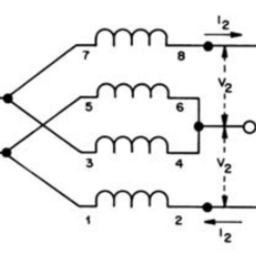
BTW, here’s Sevick’s soak test description.
Updated comment from 12/10/22


Leave a Reply