So I’ve gone around the block on this one. Tried a bunch of designs, studied a bunch of others and finally designed my own!
The goals of the bias circuit include:
- Present a well regulated, extremely clean DC bias to the gates
- Allow for a very stable and accurate adjustability
- Compensate the bias at -2.5mV/degC temperature rise
- Keep the LDMOS biased whereby regardless of temperature, the bias current remains constant.
#4 is the key. As a LDMOS heats up, Ids will rise and the gain changes, causing the LDMOS to drift into a less linear operating region.
How can we manage this? Well, as usual there are many ways. Some of the more common methods include:
- Dedicated temperature compensating analog bias chips
- Discrete Bias circuits involving a regulator, OP Amp and a temperature sensor (transistor, diode, thermistor, etc)
- “High end” digital bias chips which involve a editable lookup table and require programming with a MCU
- Full analog circuit involving a regulator, resistor dividing network and a thermistor
After trying 1 & 2 above and not being interested in 3, I decided to design my own…#4.
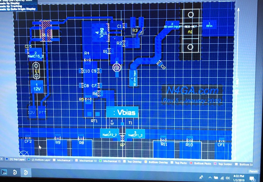
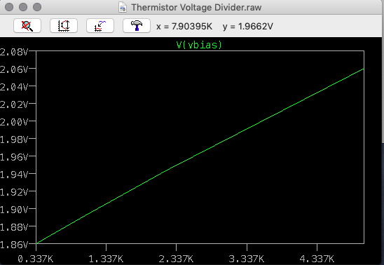
After a month or so of running SPICE simulations in my spare time (primarily while watching sports on TV), I arrived at a design using a LM317 adjustable regulator, a 5k NTC thermistor and a well chosen voltage divider network.

Nice thing is, the temp curve of a 5k NTC therm is linear so I could design around this. It all came down to scaling to get the bias adjustable in the tight little range required (~3 to 3.5V) while keeping the slope of the temperature adjustment curve at -2.5mV/degC.
So in layman’s terms: get the slope to -2.5mV/degC and center the curve at a specific voltage of ~3.25V. Fun little puzzle requiring a lot of .STEP and Monte Carlo in SPICE.
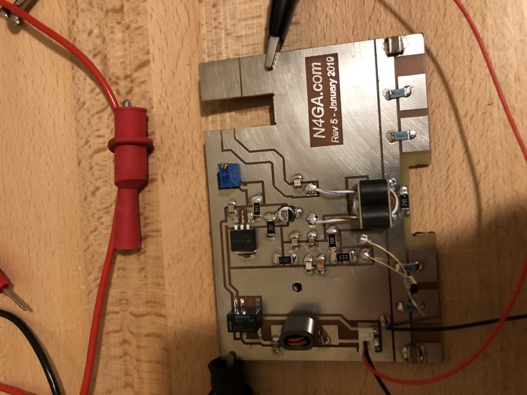
The new circuit is built and tested and works flawlessly. I can set the amp for 4A idle current at room temp, heat it up so hot you can’t even begin to touch the heat sink, and the idle current will still be 4A.

Mission Accomplished!
Also see related articles:


Leave a Reply