Testing a 2x MRFX1K80H LDMOS Amp

The other day, a fellow amp building buddy asked me what I was seeing for performance on my double MRFX1K80H LDMOS Amp.

I pulled out the ole dummy load and set up this quick test bench.
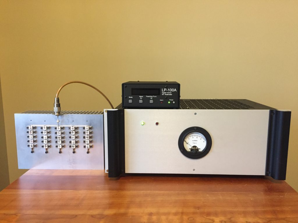
 

On the left you can see the home made ~4kW dummy load. Amp in the middle and LP-100A on top, set in Tune Mode.

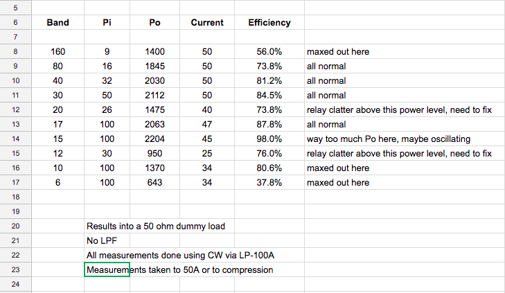
Ran through the bands and tested to either 50A (just below what the power supply will do) OR compression. Obtained the results below.

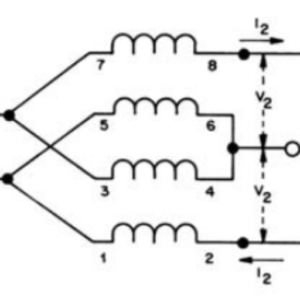
This is pretty typical where you have lower performance at the extremes. These are standard broadband trade-offs when you are trying to cover 1-50Mhz with the same output TLTs.

I have a little relay clatter on a couple of bands, which means my relay delay circuit is taking on RF on those bands, above the indicated power. This only happens on a continuous wave and never shows up on SSB regardless of power level. It’s an easy fix requiring a simple capacitor to ground somewhere. I’ll get around to it eventually. 🙂

Otherwise, got to LOVE the performance of these amplifiers!

Rob
 

Comments

11 responses to “Testing a 2x MRFX1K80H LDMOS Amp”

  1. darrell wyatt Avatar
    darrell wyatt

    Wow Awesome Rob. Why is the eff. so low on 10m? Do you have any idea? Is it the mix of the input circuit core? Thats is certainly very impressive!!

    1. N4GA Avatar
      N4GA

      Darrell,

      The efficiency is quite good on 10m, the problem is Po hits a ceiling. This makes me think I may have some resonance to ground on the input side in this frequency range. I never operate on 10m so it went to the back burner. Also, in general my output TLTs have not been fully optimized to be the best compromise from 1-50Mhz. Future projects!

  2. john simmons Avatar
    john simmons

    Have you tried varying the power supply voltage to see if the efficiency changes?

    1. N4GA Avatar
      N4GA

      Hi John,

      I have not. I’m fixed at 51.4V with my power supply. The efficiencies are good (too good really) except at the two extremes – 160m and 6m. This is where the TLT tradeoffs show up and this is fully expected. One could either live with it, or start experimenting with the TLTs, knowing that anything done to improve one end will hurt the other end. I think a couple more turns in my 2nd 4:1 TLT would totally fix 160m, so that’s probably my next experiment.

  3. Baruch zilbershatz Avatar
    Baruch zilbershatz

    what is your total line length on the first 1:4 trafo?

    1. N4GA - Rob Avatar
      N4GA – Rob

      Hi Baruch,

      It’s ~16 inches, or .4064 meters.

  4. Vinny Stipo Avatar

    Is the Pin data before attenuation, 10db?

    -KM2W

    1. N4GA - Rob Avatar
      N4GA – Rob

      Vinny – yes. Sorry I did not point that out. Kind of important!

      1. Vinny Stipo Avatar

        Did you ever figure out what was going on with 10 meters? I have one of Baruch’s boards, (similar back to back 4:1s) And I’m seeing the same compression at 1300w Pout, very similar performance as you’ve shared here on other bands.

        Thanks for posting all your experiments and designs! I’m a big fan!

        -KM2W

  5. Jim, N7CXI Avatar
    Jim, N7CXI

    Do you have any comparitive tests against 9:1 transformers running at a similar operating point?

    There seems to be a movement to go to 16:1 at 1KW output levels. I have a single-board amp with 2 MRFE6VP61K25HS running each package in parallel and the packages in push-pull. It’s 9:1s, and compresses around 1200W output. I’m leaning toward two modules and a combiner for the next one simply because I run both AM and RTTY, and at 1KW output my pallet can’t move enough heat for 100% duty cycle. (AM is 250W/1KW, but the inefficiency at the carrier level makes it just about as bad as RTTY)

    1. N4GA - Rob Avatar
      N4GA – Rob

      Jim,

      We don’t have a lot of choices on these impedance ratios, 4:1, 9:1, 16:1 basically. So for me, i just get as close as possible to end up at close to 50 ohms based on Vds and the average output level I am designing the pallet for. To stray way away from theoretical on that makes no sense to me.

      For example, here’s a chart showing Xo (impedance at the drains), then after 9:1, or 4:1, or 16:1 all at 51.4Vds:

Leave a Reply

Your email address will not be published. Required fields are marked *