Anyone that’s corresponded with me about my amplifier designs knows that my goal is to design a broadband LDMOS amplifier capable of running acceptably clean without LPF filtering.
However, there’s “acceptably clean” and then there’s the FCC 97.307 Emission standards that states this:
(d) For transmitters installed after January 1, 2003, the mean power of any spurious emission from a station transmitter or external RF power amplifier transmitting on a frequency below 30 MHz must be at least 43 dB below the mean power of the fundamental emission.
“..any spurious emission” refers to harmonics, like the 2nd, 3rd, etc., as well as spurs. In my experience with this amplifier topology, the 3rd is by far the largest harmonic and if any spurs are present, they are very small.
But what about IMD?
I get this question a lot!
IMD and harmonics are two different things, but related through physics.
IMD pertains to distortion that surrounds the fundamental frequency, typically inside the bandwidth of the mode, like 3kHz for SSB. If IMD is really poor, it can expand out much farther like 10kHz, but it will never stretch out to even the second harmonic.
There is no FCC spec for IMD for Amateur Radio, though I do not advocate designers ignore IMD. Really poor IMD typically looks like splatter, sounds like distorted audio, and often extends well outside of the mode bandwidth.
Good news is, in a LDMOS push-pull AB amplifier, IMD is directly correlated with the 3rd harmonic, which again, is also the strongest harmonic. Designing for a low 3rd covers just about anything you can do to lower IMD with these amps, outside of APD. If you lower harmonics, you lower IMD and there are no special tricks for lowering IMD on its own.

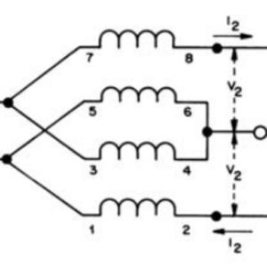
Nice image lifted from the web showing the relationship between harmonics and IMD.
What about -43dB?
Now let’s take a look at the -43dB FCC spec and how difficult it is without LPFs.
500W fundamental with a 3rd harmonic down -43dB is 0.025W or 2.5 hundredths of a watt allowed.
1500W fundamental with a 3rd harmonic down -43dB is 0.075W or 7.5 hundredths of a watt allowed.
Who knew the FCC were such purists!
How do the commercial PROs deliver 1500W cleanly?
In most commercial LDMOS “linear” amps, without the LPF, or pre-LPF, the 3rd will only be down 10dB to 15dB, not anywhere close to -43dB. A sine wave with a -10dB 3rd is basically a wavy-topped square wave.
At 1.5Kw, with the a 3rd harmonic down only 10dB, this is 150W, plus the combined power of all the other harmonics, that has to be filtered by the LPF. This is why the LPF is almost always the first thing to get smoked in these amplifiers.
If any effort went into making these commercial amps with a -10dB 3rd harmonic run a lot cleaner, then none of the companies could deliver 1500W. Why? A square wave has twice the power of a sine wave. If you start with a 2kW square wave and filter out 500W of combined harmonics, you can end up with a 1500W sine wave.
This also explains the relatively poor efficiency with these amps. We’re tossing a lot of power in into the LPFs and into the heat sinks!
So what’s my strategy?
So given all this, how in the world do I think I might get a -43 dB 3rd without a LPF?
Here are some of the strategies:
- I’m operating below 700W and this is KEY at 50V.
- I’m concentrating on single device LDMOS amps. Much cleaner by default. The single package gemini devices are near-perfectly matched.
- I’m experimenting with higher Vdd voltages for higher circuit impedances.
- I’m working on unique CMFCs with higher mutual inductance, lower stray inductance and lower inductive reactance.
- I’m working on optimized short-path well grounded low impedance circuit boards.
- I’m factoring what’s going on inside the LDMOS: capacitances, RDSon, and varying voltages and heat.
- I’m using 9:1 TLTs to constrain the voltage swings in the FETs, reducing the non-linear capacitive effects as VDS swings from 0V to 50V.
- Bias – too much to go over here, but counterintuitive for sure.
The challenge starts out fairly easy at 1Mhz and gets exponentially more difficult as the frequency rises to 30Mhz.
Last, I’m also aware that given the non-linear LDMOS devices we have to work with and the old school non-complimentary topologies we are limited to, reaching -43dB without LPFs, from 1-30Mhz at say 500-700W is likely not in the cards!
HOWEVER, achieving something more realistic, that is still quite acceptable from an interference standpoint may well be!
I’ll end with this
20 meters, 14Mhz, 3rd harmonic is 42Mhz. If you’re transmitting 500W on 20m and you have a signal on your 3rd harmonic that’s -35dB (vs the -43dB FCC spec) then you’re transmitting 15.8 hundredths of a watt at 42Mhz.
I’ve achieved that today and much better on the lower bands.
I think that’s “acceptably clean..”
But I continue to try to lower it.
Leave a Reply